Specifications
Teraview Terapulse 4000 Spectrometer
| Frequency | 5 - 100 cm-1 |
| Time resolution | 0.1 ps |
| Temperature range | 1.5 K~ 300 K |
| Magnetic field | up to 10 Tesla |
| Measurable spectra |
Complex transmission coefficient |
The principle of the THz time domain spectrometer
The THz time domain spectrometer consists of several optical components: ultra-short NIR laser, beam splitter, photoconductive antennas, and optical delay stage as described in Figure 1a. The ultra-short NIR laser is split into two at the beam splitter and one travels to the THz emitter. Our THz emitter utilizes photoconductive antenna on top of low temperature grown GaAs substrate. The incoming NIR laser activates the emitter by generating the photocarriers in the vicinity of the antenna which last several picoseconds (see Figure 1b). The carriers will be accelerated by the static DC electric field emitting the coherent THz radiation. Here, the frequency range of the emitted light is related to the hot carrier lifetime. Thus, by switching the substrate, modification of the frequency of the emitted light can be achieved.

One can use this THz light to measure samples in transmission or reflection geometry. For the different geometry, different optical stages are required. In both cases, parabolic mirrors are located in the beam path to focus or collimate the beam profile. Additionally, the optical path needs to be vacuumed or purged by N2 gas to protect the spectra from the H2O molecular absorptions.
Detecting process is a reversal process of the emission. In this case, the THz radiation is the source of the electric field. At the same time when the THz light pass through the detector, the other half of the NIR laser hits the GaAs substrate and generates the carriers in the substrate of the detector. Then, the current can flow between the upper and lower side of the antenna which can be measured. However, due to the short period of the carrier lifetime, the detection is limited to an extremely short slice of the overall waveform. To overcome this limit, the optical delay line is used to control the measuring time point regarding the entire electric field waveform. Repeated sampling with varied delay times completes the entire transient electric field profile, E(t).
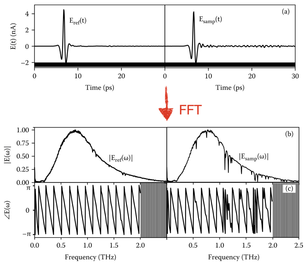
The electric field signal itself can possess information about the material, however for the spectroscopic study, one needs to transform the time domain signal to the frequency domain one. For that we use fast Fourier transform as depicted in Figure. 2. The direct measurement of the electric field allows one to access to the phase part of the signal as well. Thus, complete information of the optical properties can be obtained.
In practical uses, one also need to measure the reference signal for the quantitative information. For the transmission geometry, an empty hole is served and for the reflection a gold mirror can be a reference.
Then one can obtain transmission coefficient as t҃ (ω) = E sample (ω)/E reference (ω). The complex transmission coefficient is connected to the complex index of refraction as follow: t҃ (ω) = 2/[1+n҃(ω)]. Other optical constants can be also calculated by the relations between optical constants.
Major advantages of time domain THz spectroscopy
The time domain THz spectroscopy measures the THz electric field of a material as a function of time. The first advantage comes along with the direct measurement of the electric field. Unlike other spectroscopic techniques which collect the intensity of the signal, a direct measurement of an electric field gives the access to the phase part of the spectra. Therefore, one can obtain complex optical constants without the need of Kramer-Kronig relation. This is a huge advantage as one can exclude unnecessary errors or uncertainties. The second advantage is the time resolution. The working principle of the THz time domain spectrometer relies on an optically gated photoconductive antenna with ultra-short laser. This allows one to access to the time scale of the optical phenomena and provides additional degree of freedom to control the time window to select desired optical effect or remove undesired ones.
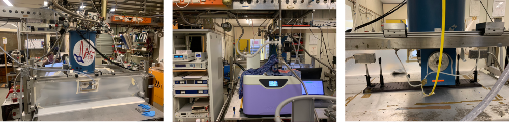
Current setup
Our current time domain THz spectroscopy setup utilizes the commercial TeraView Terapulse 4000 spectrometer. This spectrometer provides two different measurement channels, one is internal and the other is external. For the internal chamber, we installed a continuous flow LiHe cryostat for temperature dependent measurement down to 8 K. The external channel is used for the magneto-THz measurement with magnetic field up to 10 T and temperature down to 1.5 K. Additional improvement for the setup is underway including Faraday rotation and reflection geometry.
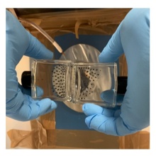
Ferrofluids under magnetic field
For the magneto-THz setup, visualizing the magnetic field could help to optimize the setup configuration. For this purpose, the ferrofluids can be utilized. The ferrofluids are made of ferromagnetic nano particles in a solution which aligns to the field direction. The visualized stray fields of the superconducting magnet are taken account into the instrumentation to minimize the any interferences with the electronic devices.

References:
Dexheimer. Terahertz Spectroscopy: Principle and Application (2007) CRC Press.
Dressel. Electrodynamics of Solids: Optical Properties of Electrons in Matter (2002) Cambridge University Press